WiFi “Ghost Frame”, What Is It?
A WiFi Ghost frame is a term widely used in the WiFi community lately. It is not a part of the 802.11 standard, it is just a term many uses.
Some say it is a frame the receiver don’t hear, other say the receiver don’t understand. Both are wrong.
So what is it?. I will try to explain.
Contraints
I am only talking about frames in the 5GHz band and non-HT, HT and VHT frame formats. HE frame formats is not considered.
I assume the reader knows something about 802.11. I don’t explain the basic stuff.
The wireless frame in this article is sent by the AP.
Background
An 802.11 frame consists mainly of two parts. The Preamble (also called the Physical header), and the Data field, like this

The Preamble is always sent with BPSK modulation and 1/2 coding. It has different contents depended whether the Data field is non-HT, HT or VHT frame, but the modulation and coding are always BPSK 1/2. The Data field is sent with a modulation and coding scheme decided by the transmitter. The modulation scheme can be BPSK, QPSK, 16-QAM, 64-QAM, or 256-QAM. And there are different coding schemes. BPSK 1/2 is a more robust modulation and coding scheme than the others and will therefore have a “longer” range.
This can be shown in a figure like this:
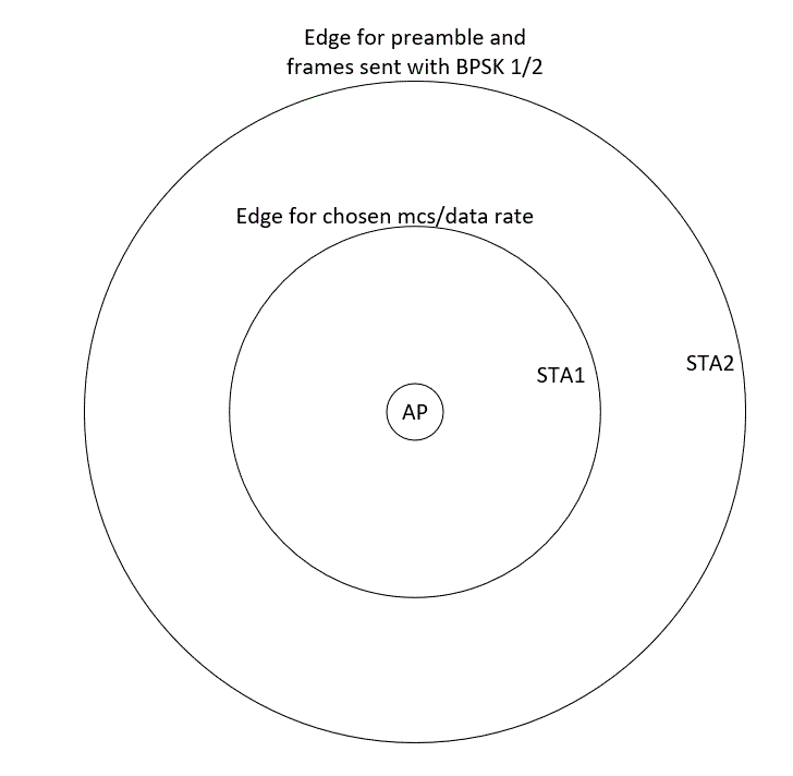
Communication between the AP and STA1 will be done with an appropriate mcs-index/data rate. STA2 will in the case hear/receive the full-frame from the AP, but it will only successfully demodulate the preamble unless the frame is a 6mbs (BPSK 1/2) frame. The data field in the frame from the AP will not be successfully demodulated by STA2 and it will not be able to extract the information in it.
A scenario with minimum basic rate set to 12mbs
So let us make a scenario where the minimum basic rate in the BSS is set to 12mbs (QPSK 1/2). This means many of the frames in the BSS is sent at 12mbs, frames like Beacon and the other management frames, and most of the control frames. Data frames are usually sent with higher rates. According to the standard, a station needs an RSSI of -79dBm to be able to receive and successfully demodulate a 12mbs frame (QPSK 1/2), while it needs -82dBm for 6mbs (BPSK 1/2). And if we have a designed network with cell edges at -67dBm, it will look like this:
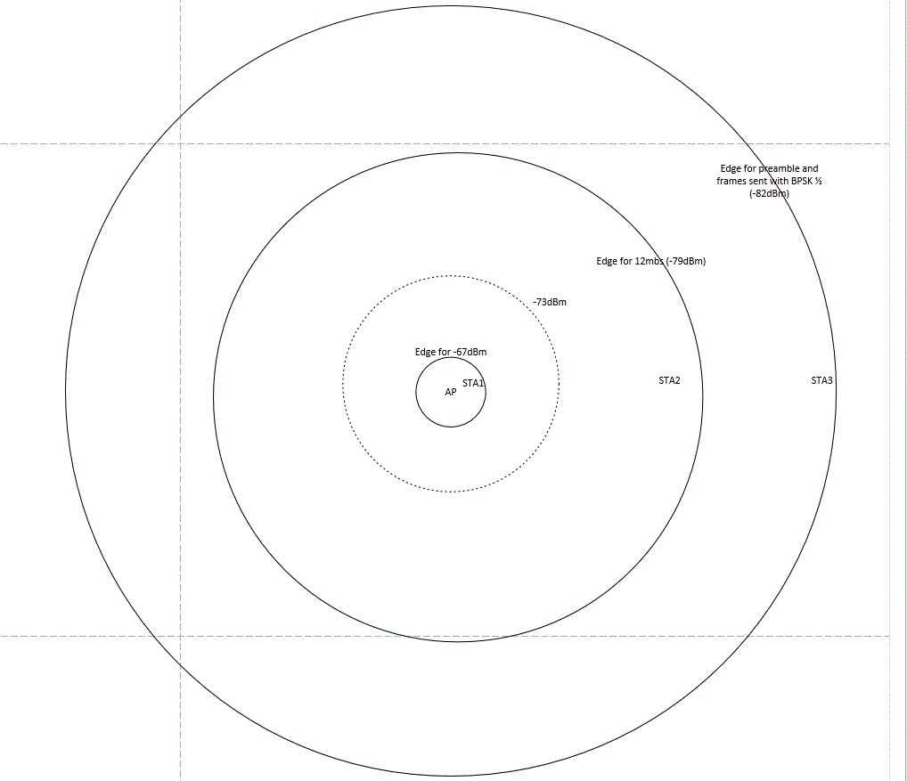
In this figure I have used these parameters:
– free space path loss (FSPL)
– a 6dB degradation of RSSI for each doubling of the distance
– cell size for the APs coverage area till -67dBm (often called the “want” area)
In figure 3 we have STA1 inside our designed coverage cell, STA2 is inside the edge for successfully demodulating of the 12mbs frames and STA3 is in an area where it will successfully demodulate the preamble from the AP, but not the data field of the frame.
So what happens at STA3
Let us consider a frame sent from the AP at 12mbs and see what happens at STA3.
First STA3 will receive the preamble with BPSK 1/2 and later the data field with QPSK 1/2.
STA3 knows, based on the standard, that the preamble is modulated with BPSK 1/2. Since this is an 12mbs frame it is also a 802.11a frame. The Signal field in the preamble will therefore tell about the data rate for the data field (12 mbs or QPSK 1/2).
If it was a mcs frame, the preamble would have an additional field (HT/VHT preamble) which informs of the data rate for the data field
Demodulation of this frame
If we look at the constellation mapper for BPSK and QPSK from the 802.11 standards it looks like this:
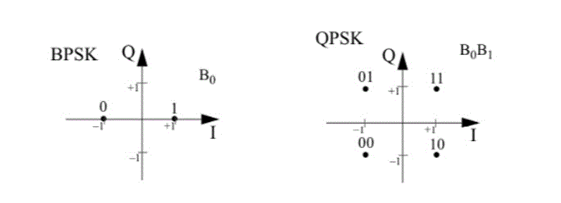
During demodulation, the receiver does a Fast Fourier Transform. The FFT basically interpret the amplitude and phase of each subcarrier and the output is a complex number with this format:
d=(I+jQ) x Kmod. We will not consider the Kmod now and assume it is 1
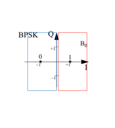
For the preamble, the receiver knows it is BPSK and the Q value in the formula is not considered. As long it predicts each subcarrier has a phase either in the first or the fourth quadrant it gives a result d=1 and it is a bit value of “1”. If the phase for each subcarrier is in the second or the third quadrant it will give a result of d=-1 and a bit value of “0”. Like this:
Keith Parsons have a great video on modulation,
Since STA3 barely is able to demodulate the preamble correctly we can assume the result of the FFT for all subcarriers will be all over the first and fourth quadrant (red rectangle) for “1”, and likewise for “0” in the second and third quadrant (blue rectangle).
Next, during the reception of the data field, the energy in the signal is still the same, but this time each subcarrier FFT phase result must hit inside a single quadrant to give its correct bit value. For example, a hit in the first quadrant (d=1+j) will give a bit value of “11”.
But the quality of the received signal is the same as for the preamble. Since we assumed the result from the FFT will hit all around in the first and fourth quadrant for a “1” for BPSK, the result will for a phase value that should have given a bit value of “11” be like this:
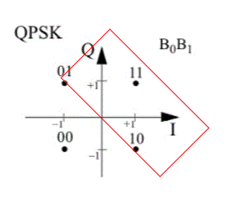
This will happen for every subcarrier in a symbol. For some subcarriers, the FFT will predict the correct value of d=1+j (11). But for other subcarriers, the FFT will predict either d=-1+j (01) or d=1-j (10). The FEC (forward error correction) build into the decoder will be able to correct some of the bit values, but not all.
The reception can fail here if the receiver is not able to extract the Service field of the data field correctly.
If the receiver sends the demodulated bit values up to the MAC layer, the bit pattern is processed there. One of the things that happen in the MAC layer is to find the Type and Subtype field in the 802.11 MAC header to decide what type of frame it is, and at last the full data field will be checked with a CRC control. But since there is a lot of bit faults in the bitstream, it will fail somewhere.
Probably, the reception will fail in the de-modulator, at layer 1. But if the bit pattern is been sent to the MAC layer it will fail there, at layer 2.
To summarize this for STA3:
- The preamble (BPSK 1/2) will be successfully received, demodulated and, understood in the receiver, at layer 1
- The data field (QPSK 1/2) is received with the same power level at the receiver, at layer 1. But because the demodulation process output will have so many fault bit values it will probably fail at layer 1
- If the bit pattern is sent up till the MAC layer, at layer 2, it will fail there
- So, the full-frame is heard and received, at least at layer 1. But it will fail and will not be interpreted at layer 2 or higher.
- STA3 will therefore do at least two thing
- Understand the preamble with the Signal field and can calculate the duration of this frame
- It will not be able to receive the NAV-timer from the MAC header, but it will sense/hear 802.11 modulated signal patterns during the full duration of the frame. If it not going into sleep mode for this duration of time
What are the consequences?
First of all, this does not happen inside of the -67dBm cell coverage of our AP. It is either in another BSS or if we, in our network have two BSSs on the same channel at some distance away from each other
If STA3 is a non-AP STA (client) it will have to stay quiet during the duration of the frame
If STA3 is an AP it will have to stay quiet during the duration of the frame, and it could report at airtime utilization value based on the duration.
If STA3 is a spectrum analyzer it could visualize the energy received
If STA3 is a capturing device it would not show anything
How to mitigate this behavior?
If we let 6mbs be the minimum basic rate, both the preamble and the data field for, at least the control and management frames, will be using BPSK 1/2 modulation and coding scheme, and the Beacons/BSS will be visible in a Wlan scanner tool. And all the 6mbs frames could be captured for protocol analyses.
The BSS Coloring feature in 802.11ax would be perfect to use to mitigate this challenge. But that could be described in another article. source
The closing
I hope this is useful.
I have learned a lot.
Please, give feedback if you want
Download Softare Below
/Ghost_ESP Buy here
Purchase GPS Hardware Below
GhostESP- The ESP32-C6 Buy Here
supe it up with a GPS Module
GPS/GNSS Module by Rabbit-Labs Buy Here
