Hacker Tool Kit & Pen Tester Kit HackerBox 0073 LAN Lord
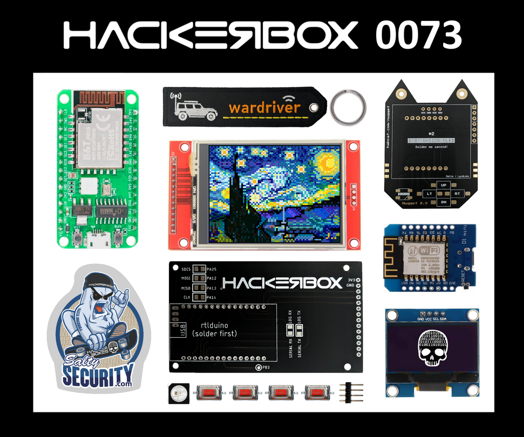
Welcome to HackerBox 0073. We will explore Wi-Fi channels and frequencies, configure the ESP8266 D1 Mini SoC, assemble the Open Source Wi-Fi Nugget, leverage the Wi-Fi Nugget as a communications security and hacking tool, introduce the Rtlduino dual-frequency wireless SoC, assemble a full-color TFT display platform for the Rtlduino, and leverage the platform to implement a Wi-Fi channel mapping tool capable of operating on both 2.4GHz and 5GHz wireless bands.
HackerBoxes is the monthly subscription box for enthusiasts of electronics and computer technology – Hardware Hackers – The Dreamers of Dreams.
There is a wealth of information for current and prospective members in the HackerBoxes FAQ. Almost all of the non-technical support emails that we receive are already answered there, so we’d really appreciate it if you can take a few minutes to read the FAQ.
Supplies
This Instructable contains information for getting started with HackerBox 0073. The full box contents are listed on the product page for HackerBox 0073 where the box is also available for purchase while supplies last. If you would like to automatically receive a HackerBox like this right in your mailbox each month with a $15 discount, you can subscribe at HackerBoxes.com and join the revolution!
A soldering iron, solder, and basic soldering tools are generally needed to work on the monthly HackerBox. A computer for running software tools is also required. Have a look at the HackerBox Core Workshop for a set of basic tools and a wide array of introductory activities and experiments.
Most importantly, you will need a sense of adventure, hacker spirit, patience, and curiosity. Building and experimenting with electronics, while very rewarding, can be tricky, challenging, and even frustrating at times. The goal is progress, not perfection. When you persist and enjoy the adventure, a great deal of satisfaction can be derived from this hobby. Take each step slowly, mind the details, and don’t be afraid to ask for help.
Step 1: Wi-Fi Frequencies and Channels
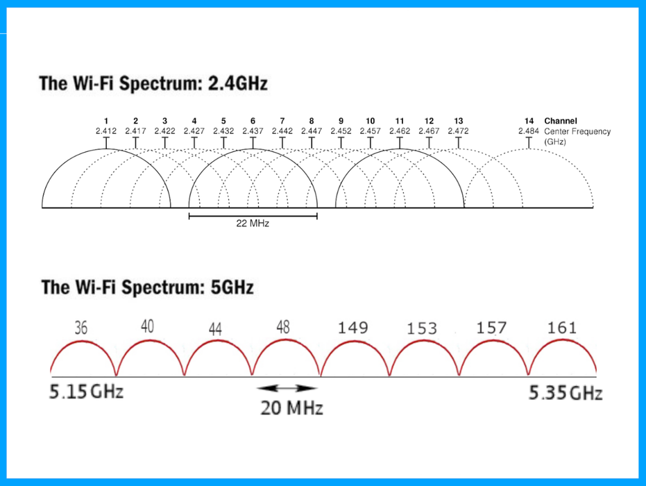
The 802.11 standard provides several distinct radio frequency ranges for use in Wi-Fi communications. These range from 1000 MHz to 60 GHz bands. Currently, the most commonly used frequency bands are 2.4GHz and 5GHz.
Each range is divided into multiple channels numbered at 5 MHz spacing. Although channels are numbered at 5 MHz spacing, transmitters generally occupy at least 20 MHz, and standards allow for channels to be bonded together to form wider channels for higher throughput.
Each Wi-Fi channel is a small segment of a frequency through which wireless networks can send and receive data. The 2.4Ghz band is made up of 14 channels, 3 of which are non-overlapping channels. In the illustration the non-overlapping channels are shown with solid lines while the others are dotted. The 5Ghz band has 23 channels, 8 of which are defined for indoor routers and access points.
The 2.4GHz band provides a wide coverage area and is better at penetrating solid objects. It has a maximum data speed of 150Mbps. Unfortunately, 2.4GHz frequencies can suffer more interference and disturbance.
The 5 GHz frequencies support higher data speeds with reduced interference, put provide narrower coverage area and are less capable of penetrating solid objects.
Step 2: ESP8266 D1 Mini
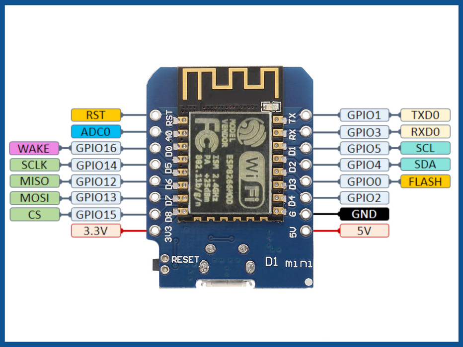
The D1 Mini Module is based on the ESP8266 SOC. The ESP8266 SOC includes a microcontroller core, Wi-Fi circuitry, and an integrated TCP/IP protocol stack. The ESP8266 is capable of running code directly on its MCU core, or the ESP8266 can act as a communication peripheral to provide WiFi functionality to another microcontroller.
ESP8266 with the Arduino IDE
The D1 Mini Module can be programmed through the Arduino IDE. To set up the ESP8266 support within the Arduino IDE, follow Steps 1-5 of this tutorial.
In the IDE, select Tools > Board > ESP8266 Boards > LOLIN WEMOS D1 R2 & mini
Under Tools > Port select the COM port that appears when the D1 Mini is plugged in
Blink an LED
Open and upload the sketch: File > Example > ESP8266 > Blink
Once uploaded, the Blink sketch will flash the blue LED on the D1 Mini
You can experiment with changing both delay calls in the blink sketch to 2000, run the code, and then change them both to 200 and run the code again. Verify that the LED flashes ten times faster with the 200ms delays compared to the 2000ms delays.
Scan Wi-Fi Networks
The best thing about the ESP8266 is Wi-Fi support, so let’s try it out. Grab the NetScan8266.ino sketch attached here. Program it into the D1 Mini.
Open Tools > Serial Monitor and set the baud rate to 9600.
The ESP8266 will scan for all 2.4GHz networks and then list out the SSID and RSSI of each one to the serial monitor.
Attachments
Step 3: Assemble the Wi-Fi Nugget
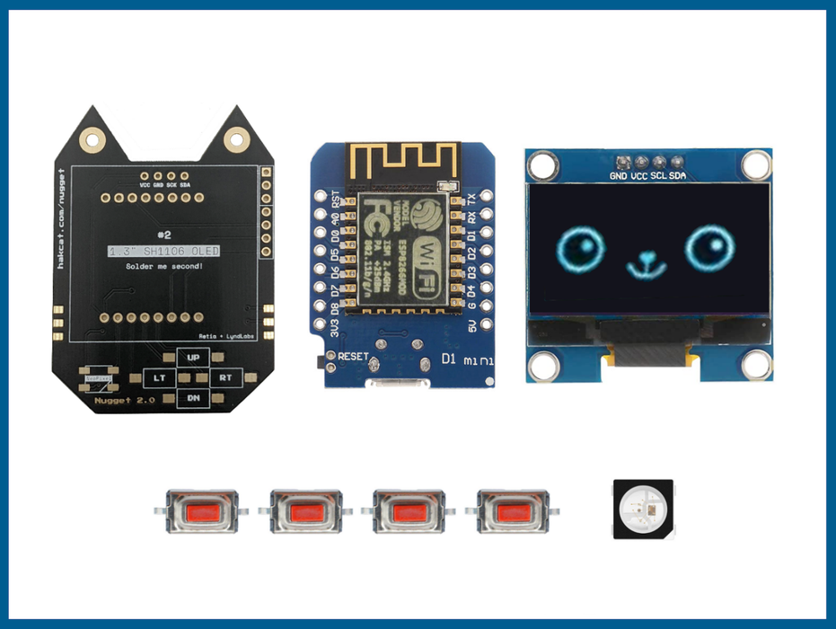
The Wi-Fi Nugget is a cool hacking platform based on the D1 Mini module with an added OLED display, four push buttons, and an RGB WS2812B LED.
The Open Source Hardware Wi-Fi Nugget was designed by skickar and alexlynd. MOAR Nuggets can be purchased from Retia.
Assembly Notes:
Start with the four pushbuttons. They are not polarized and can be oriented in either direction.
Next set the LED. It must be correctly oriented, so find the little white triangle on one corner of he LED itself and the corner marking on the PCB silk screen. Turn the LED so that these line up.
Next solder on the ESP8266 D1 Mini using the header pins. After soldering, trim the pins close the Nugget PCB
ALWAYS WEAR SAFETY GLASSES WHEN CUTTING PINS
The last item to solder is the 1.3 inch OLED Display. Prior to soldering the OLED, it is a good idea to put some electrical tape (or carboard or plastic or whatever) between the display and the D1 mini pins that protrude underneath. This can help prevent things from shorting out and also makes the finished product feel nice and solid.
Shall We Play A Game?
This one has nothing to do with LANs, but games are always fun.
Give the attached arkanug.ino a shot.
Note that arkanug requires first setting up the library ssd1306 (by Alexey Dynda) through the Arduino IDE library manager.
Attachments
Step 4: Wi-Fi Nugget Projects
This video demonstrates the power and versatility of the little ESP8266 SoC as a security tool.
Wi-Fi Nugget Packet Monitor code
Wi-Fi Nugget Quick Start video
Find additional videos and projects on HAK5 YouTube Channel
Search for “WiFi Nugget” on YouTube
Step 5: Rtlduino RTL8720DN Dual-Band IoT Module
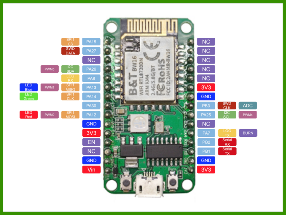
The Rtlduino development board includes the BW16 dual-band Wi-Fi+Bluetooth SoC module. The BW16 is based on the RTL8720DN chip from Realtek (datasheet). The RTL8720 supports dual band (2.4GHz and 5GHz) Wireless LAN (Wi-Fi) and Bluetooth Low Energy (BLE 5.0). The RTL8720 incorporates two processing cores:
The first core is a high-performance MCU called the KM4. This high-performance core is ARM Cortex-M33 instruction set compatible (Armv8-M). The KM4 MCU is a 32-bit core supporting enhanced debug features, floating point computation, DSP instructions and incorporates a 3-stage pipeline.
The second core is a low power MCU called the KM0. This low-power core is ARM Cortex-M23 instruction set compatible (Armv8-M). The KM0 MCU is an energy-efficient “coprocessor” operating on a simple instruction set and reduced code size while remaining code-compatible and tool-compatible with the high-performance KM4 core.
Features:
- Dual Band Wi-Fi: 2.4GHz and 5GHz
- 802.11a/b/g/n
- Supports HT20/HT40 mode
- Low-power modes: beacon monitoring, receiver, suspend
- Built-in AES/DES/SHA hardware engine
- TrustZone-M and Secure Boot
- SWD debug protection and prohibit mode
- BLE and BT5.0 Bluetooth
- High-Power Bluetooth Amplifier (7dBm)
- Shared Wi-Fi and BT Antenna
- Wi-Fi Modes: STA/AP/STA+AP
Reference: BW16 Documentation (Ai-Thinker)
MAKING FIRST CONTACT:
We suggest making first contact with, and reprogramming, the Rtlduino module prior to soldering the module or connecting anything to its pins. Simply connect the microUSB port on the Rtlduino to your PC and launch a serial terminal program such as the Arduino IDE Serial Monitor or PuTTY. Set the baud rate of the terminal to 38,400.
The terminal should display “AT COMMAND READY” and a # prompt from the Rtlduino. You can type “AT” through the terminal and receive an “OK” in response.
This AT command interface (reminiscent of Hayes modems and initial ESP8266 offerings) is provided by the firmware loaded into the Rtlduino at the factory. You can remove this firmware and run your own programs.
Step 6: Rtlduino – Removing the Factory Firmware

There are three different methods suggested on this forum for clearing the factory firmware on the Rtlduino. We have had success with Method 1 which performs an over the air (OTA) flash using your Wi-Fi network. The process is a little convoluted, so we’ve attempted to restate it below:
STEP 1. Download the AmebaD SDK
The SDK can be found at the ambiot GitHub.
STEP 2. Connect the Rtlduino to your Wi-Fi Network
This is done through the Rtlduino AP command interface
From the serial terminal, enter the AT Command: ATPN=SSID,password
Wait for the response: #ATPN OK
Note that the Wi-Fi network used needs to be the same one that your PC is on
STEP 3. Generate the OTA.bin File
Among the SDK files downloaded above, navigate to the folder “tools\AmbaD\Image_Tool”
Run image_tool.exe
Click the “Generate” tab
In the “Generate Target” dropdown, select OTA_All
Check the box next to “Bin 3”
On that same line, hit browse and navigate to that same “Image_Tool” folder
From that folder, select “imgtool_flashloader_amebad.bin”
Hit “Generate”
To save the output file, navigate to “tools\DownloadServer” among the same SDK files
Save the file into that folder as “ota.bin”
STEP 4. Find the IP Address of your PC
Open a Windows Command Prompt
Run “ipconfig”
Make a note of the full address shown as “IPv4 Address”
STEP 5. Launch the OTA Download Server
From the Windows Command Prompt, change the directory to:
“\tools\DownloadServer” (where you saved ota.bin)
Run start.bat
The tool will display “Listening on Port (NNNN) … Waiting for client…”
Make a note of that port number.
STEP 6. Connect the OTA Client (the Rtlduino)
Go back to the serial terminal window
Enter the AT Command:
ATSO=IP_address,port_number
The response should show: ”Erase is ongoing…” and then eventually complete.
STEP 7. Check the Rtlduino Firmware Image
Press the reset button (RST) on the Rtlduino to check the serial output has updated
Step 7: Rtlduino – Configure and Test Arduino Tools
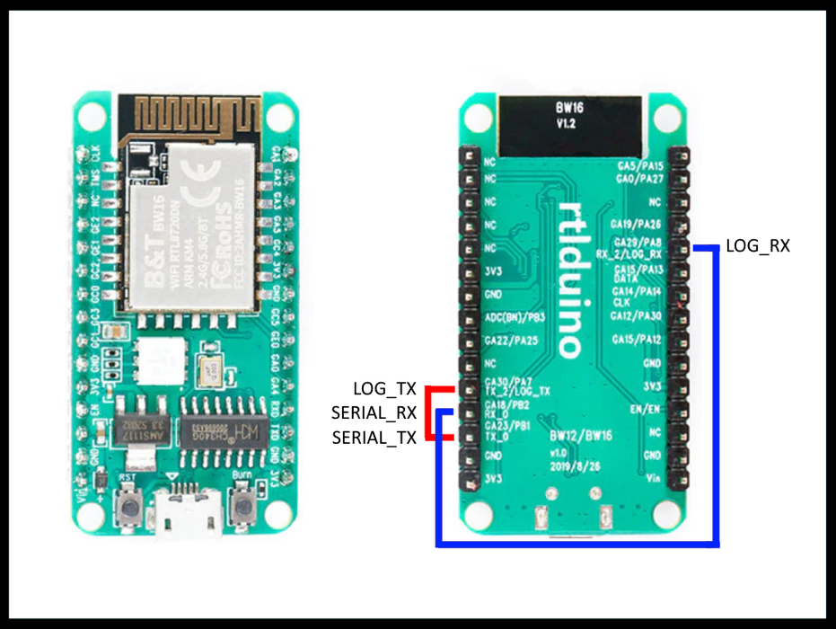
First we need to link together two serial ports of the Rtlduino. These are the Main Serial UART and the Log UART. We can link these two ports using two female-female jumpers on the pins shown in the image. The Serial_RX pin is connected to the Log_RX pin. The Serial_TX pin is connected to the Log_TX pin.
Next, install the Arduino IDE (this is probably already done)
Visit the GitHub repo for the Ameba Arduino SDK
Follow the instructions there for adding the additional board manager URL into the IDE
Follow the instructions to install the board manager for “Realtek Ameba Boards”
In the IDE, Select Tools > Board > AmebaD ARM Boards > RTL8720DN(BW16)
Select the appropriate COM port
Open File > Examples > Basics > Blink
Hit the upload icon (arrow button)
After compiling the code, the IDE will show “Please enter the upload mode (wait 5s)”
Press and hold both buttons on the Rtlduino, release the RST button, wait a second, release the Burn button
Hit the RST button again to reset the board and run the newly flashed blink sketch
Repeat the process whenever uploading a sketch to the Rtlduino
The Rtlduino actually has three different on-board LEDs. The define LED_BUILTIN in the blink sketch defaults to LED_G (green). Try replacing all three instances of LED_BUILTIN in the blink sketch with LED_R or LED_B.
Step 8: Rtlduino – TFT Display Interface PCB
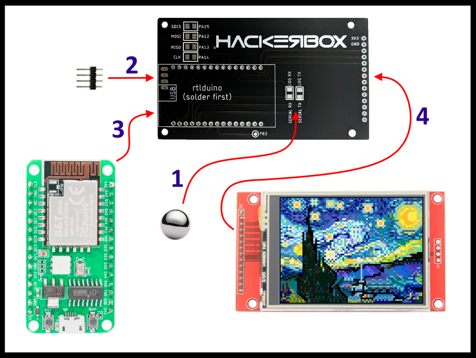
Assembly
1) Apply two solder blobs to short across the serial port pads linking RX to RX and TX to TX. These connections replace the jumper wires used in the previous step.
2) Insert the four pin header into the PCB. Position the header with the black plastic and the long pins on the TFT side of the PCB and the short pins protruding through to the side of the PCB with the HackerBox logo. Solder the four header pins.
3) Insert the Rtlduino module onto the side of the PCB with the HackerBox logo. Solder the Rtlduino header pins.
4) Insert the TFT display module on the other side of the PCB. Position the TFT module so that it is floating a bit away from the black PCB by imagining that the yellow and black plastic header insulators are 1.5-2 times thicker than they are. Keep the red PCB and the black PCB parallel while soldering the first few pins. Solder the entire long TFT header to the black PCB and then solder the four pin header to the TFT module.
Install a Library for the TFT Display
Using the IDE Library Manager, install the library “Adafruit ILI9341”
Test the TFT Display with Fractals
Open the sketch File > Examples > Adafruit ILI9341 > mandelbrot
About 18 lines down under the comment “//use SPI” find the #define for TFT_DC
change #define TFT_DC from 10 to 8
Step 9: Rtlduino TFT – PCB Specs
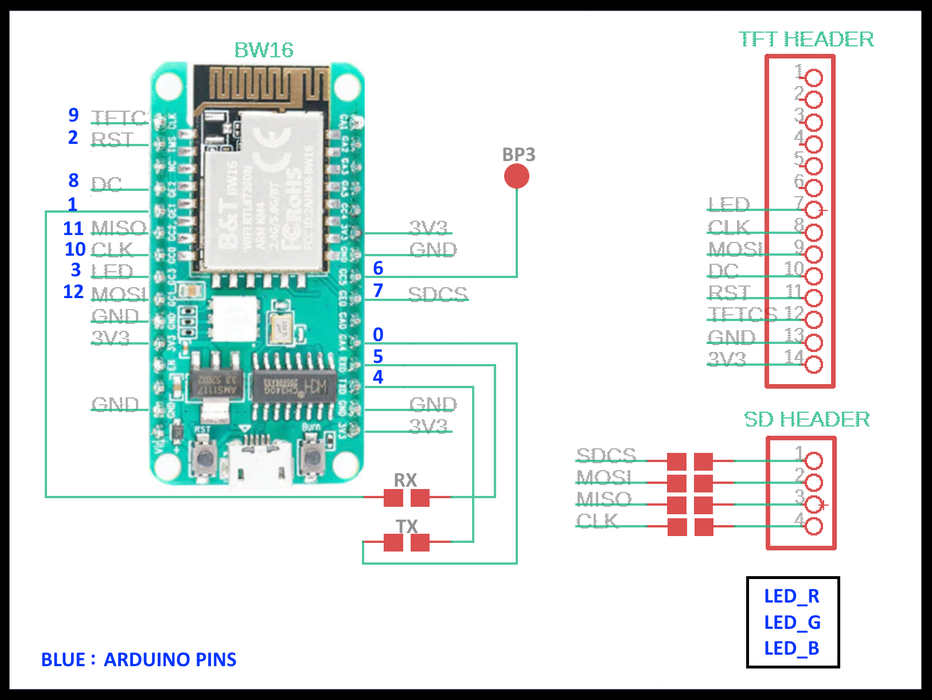
The extra jumpers points on the PCB can be shorted to connect the SD card socket
The blue numbers in the image indicate the definitions of the Rtlduino pins within the Arduino environment
Arduino pins 6 and 7 are not needed by the TFT display and may be used for other I/O connections. Arduino pin 7 connects to the jumper pad labeled PA25 on the black PCB. Arduino pin 6 connects to the circular test pad labeled PB3 on the black PCB.
Step 10: Rtlduino – Dual Frequency Wi-Fi Mapping
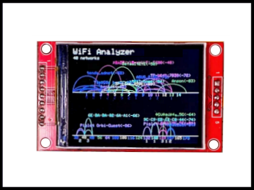
Grab the attached DualWiFiMapper.ino sketch and burn it to the Rtlduino.
Feel the power of dual frequency Wi-Fi support?
We can now work with both 2.4GHz and 5GHz wireless channels.
Attachments
Step 11: Wardriving
Wardriving is the act of searching for Wi-Fi wireless networks, usually from a moving vehicle, using a laptop or smartphone (or an SoC). Software for wardriving is freely available on the internet.
The term Wardriving is derived from the original wardialing. Wardialing is a method popularized by the film WarGames and is, in fact, named after the film. Wardialing consists of dialing every phone number in a specific sequence in search of modems.
Wardrivers often use a Wi-Fi-equipped device together with a GPS device to record the location of wireless networks. The results can then be uploaded to websites like WiGLE, openBmap or Geomena where the data is processed to form maps of the network neighborhood. There are also clients available for smartphones running Android that can upload data directly. For better range and sensitivity, antennas are built or bought, and vary from omnidirectional to highly directional. source

